 Owen Bradley
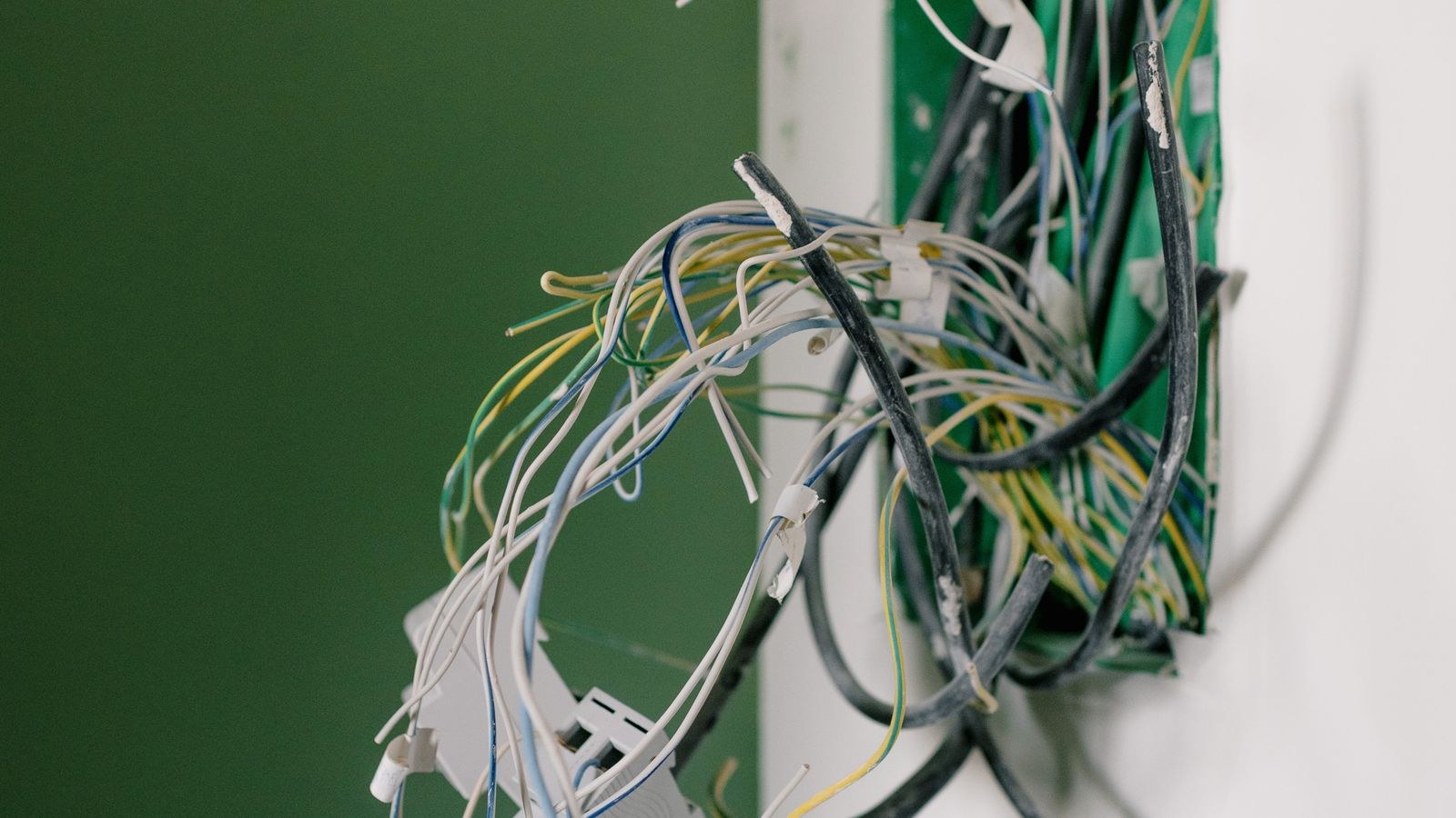
 Pull an old thermostat off the wall and you are met with a small bundle of coloured wires screwed into terminals marked with single letters. Those letters are the entire language of heating and cooling control, and once you can read them, buying a replacement stops being guesswork. This is thermostat wiring explained in plain terms: what each terminal does, why the colours are only a hint rather than a rule, and how to translate what you find into a confident compatibility check before you spend money on a new unit in 2026. You do not need to be an electrician to do this. You need a phone camera, a screwdriver, and ten unhurried minutes.
Before You Touch Anything: Safety and Documentation
Switch off power at the breaker serving your furnace, air handler, or boiler. Thermostat wiring carries only 24 volts, which will not hurt you, but touching two conductors together can blow a fuse buried on the equipment control board, and replacing that is a far bigger job than swapping a thermostat.
Once power is off, pull the thermostat body from its base. Most units unclip with a firm pull or release with a small tab. Photograph the terminal block clearly before loosening a single screw, and take a second photo from a slight angle so you can see which colour enters which slot. If any wire looks ambiguous, wrap a strip of masking tape around it and write the terminal letter on the tape. Wires have a habit of retreating into the wall cavity, so bend them gently over a pencil so they cannot slip back.
The Core Terminals and What They Control
Almost every low voltage thermostat uses a subset of the same lettered terminals. Learn these and you can read any system.
- R — 24V power in from the system transformer. This is the source that every other call switches to.
- Rh — power for the heating side, used when heating and cooling have separate transformers.
- Rc — power for the cooling side, the partner to Rh. Systems with one transformer use a jumper between them.
- W — heat call. Connecting R to W tells the furnace or boiler to fire.
- W2 — second stage of heat on multi-stage equipment.
- Y — cooling call. Connecting R to Y starts the compressor and condenser fan.
- Y2 — second stage of cooling on two-stage compressors.
- G — indoor blower fan. Used for the fan-on setting and for circulation.
- C — common, the 24V return path that lets the thermostat draw continuous power.
- O or B — heat pump reversing valve control.
- E — emergency heat on a heat pump.
- AUX — auxiliary or backup heat stage, usually electric strips.
The elegant part is that a thermostat does almost nothing clever. It is a set of switches that connect R to one or more of the other terminals when the room drifts from setpoint. Everything else lives in the equipment.
The R Terminal in Detail
R stands for the red hot leg from the transformer, and it is the only terminal supplying power. If your thermostat base has both Rh and Rc with a small metal jumper bar between them, you have a single transformer feeding both functions, which is typical of a furnace and air conditioner sharing an air handler. If the jumper is absent and two separate wires arrive, you have two transformers, common when a boiler handles heat and a separate condenser handles cooling. Removing or leaving that jumper incorrectly is one of the most frequent installation errors, and it usually shows up as a blown fuse the first time the system runs.
The C Wire and Why It Suddenly Matters
The common wire completes the 24V circuit so a thermostat can draw steady power without switching anything on. Old mechanical thermostats had no electronics and needed nothing. Battery-powered digital units survive without it. Anything with a bright display, Wi-Fi, or a colour screen effectively requires it.
Check whether one exists before assuming you need to run new cable. Very often an installer pulled a five-conductor cable, used four, and tucked the fifth, usually blue, into the back of the box unconnected. If you find a spare conductor, trace it at the furnace end to confirm it is landed on the C terminal there, then connect both ends. If there is genuinely no spare, your options are a common-wire adapter that shares an existing conductor, running new thermostat cable, or simply choosing a battery-powered model. This is a large part of why many households stay with conventional controls, and our comparison of the best non smart thermostats flags which models run happily on batteries alone.
Colour Conventions and Why You Cannot Trust Them
There is a widely used convention: red for R, white for W, yellow for Y, green for G, and blue or black for C. Heat pumps commonly use orange for O and dark blue for B. It is a helpful starting point and it is correct most of the time.
It is also not a standard anyone is obliged to follow. Installers run out of a colour, reuse an old cable, or improvise during a retrofit, and the result is a green wire on the Y terminal or a red wire doing fan duty. The rule that keeps you safe is simple: the terminal letter is the truth, the colour is a guess. Always record letters, never colours alone. If a previous installer left the old thermostat with unlabelled wires and you cannot tell what goes where, tracing each conductor at the equipment end resolves it definitively.
Reading a Heat Pump: O, B, and Auxiliary Heat
Heat pumps are where wiring diagrams get more interesting. Rather than burning fuel, a heat pump moves heat, and a reversing valve decides which direction. The O terminal energises that valve in cooling mode; the B terminal energises it in heating mode. Manufacturers differ, and wiring a thermostat as though it were the other convention produces a system that blows cold air when you ask for heat.
Because heat pumps lose capacity as outdoor temperatures fall, most installations add backup heat on the AUX terminal, and an E terminal for full emergency heat when the compressor is unavailable. A thermostat for this equipment must manage the changeover between compressor and backup intelligently, or the electric strips will run far more than necessary and your bill will reflect it. If you have identified an O or B wire behind your unit, shop specifically from the best heat pump thermostats rather than a general furnace list, since standard models simply lack the terminals.
Cooling-Only and Heat-Only Systems
Not every system uses the full terminal set. A cooling-only installation might present just R, Y, G, and possibly C. A hydronic heating system with no ducted cooling may present only two wires, R and W, because there is no blower to control and no compressor to call. Two-wire systems are perfectly normal and pair with heat-only thermostats. If your wall shows R, Y, G, and C but no W, you are looking at a cooling application, and the best AC thermostats roundup is the relevant place to shop.
Turning Your Wire Count Into a Compatibility Check
Write your terminal list down and compare it against the compatibility section on any thermostat you are considering. The logic runs in one direction: a thermostat must support every terminal you have in use. Extra terminals it offers that you do not use are harmless. Missing terminals are a hard stop.
- R, W — heat only. Any heat-only or universal model works.
- R, W, Y, G — conventional single-stage furnace and air conditioner, the most common setup.
- R, W, Y, G, C — same, with continuous power available for a powered display.
- R, Y, G, O/B, AUX, C — heat pump with backup heat. Needs a heat pump specific model.
- Rh, Rc without jumper — dual transformer system. Confirm the new unit supports separate power feeds.
Anyone weighing a connected upgrade should confirm the same terminal list first, since connectivity changes nothing about the underlying wiring requirements. Our smart thermostat buying guide works through that decision once compatibility is established, and the best smart thermostats list notes which models include a power adapter for homes with no common wire.
Common Wiring Mistakes
The most damaging error is leaving the Rh to Rc jumper installed on a two transformer system, which ties both transformers together and blows a fuse the moment either calls. The reverse mistake, removing the jumper on a single transformer system, leaves cooling completely dead because Rc receives no power.
Reversing O and B on a heat pump produces the classic complaint of cold air on a heat call. Landing the C wire on a spare terminal instead of C leaves a powered thermostat rebooting endlessly. And forcing multiple conductors under one screw, common when someone tries to improvise a common connection, causes intermittent faults that are miserable to diagnose later. One wire per terminal, every time.
Frequently Asked Questions
How many wires do I need for a basic thermostat?
Four conductors on R, W, Y, and G cover a standard furnace and air conditioner with fan control. Heat-only systems work with two. A fifth conductor on C is optional for battery models and required for most powered ones.
What if my wire colours do not match the usual convention?
Trust the terminal letters recorded from your old thermostat, not the colours. Photograph the terminal block before removing anything. If the old unit is already gone, trace each conductor to the equipment end where the letters are marked again.
Can I add a C wire without opening walls?
Frequently yes. Many cables include an unused spare conductor tucked inside the wall box or at the furnace. Failing that, a common-wire adapter installed at the equipment lets an existing conductor carry the signal, avoiding new cable entirely.
What does the G terminal do if my fan runs automatically?
G gives you manual control of the indoor blower independent of heating or cooling. It powers the fan-on setting for continuous air circulation and filtration. During a heat or cool call the equipment usually starts the blower itself, so G is not strictly required for basic operation.
Final Thoughts
Thermostat wiring looks intimidating for about five minutes, and then it becomes a short vocabulary list. R supplies power, W calls heat, Y calls cooling, G runs the fan, C completes the circuit, and O or B tells a heat pump which direction to work. Photograph the terminals, label the conductors, write down the letters, and match that list against any model you are considering. Do that before you buy and you eliminate the single most common source of returns and frustration in this entire category, whether you end up with a basic dial or something considerably more capable.