 Owen Bradley
 Soldering is the most reliable way to join LED strip lights, but also the fastest way to ruin them. The copper pads sit on a thin polyimide backing that lifts the moment it overheats, and the surface-mount LEDs nearby do not enjoy a hot iron either. The good news is that clean, permanent joints are easy once you understand that speed matters far more than heat. This walkthrough covers the tools, the correct iron temperature, how to tin pads and wires, how to match polarity, and how to test every joint before you commit the strip to a wall or a channel.
Why Solder Instead of Using Clip Connectors
Snap-on clip connectors are convenient, and for a temporary run behind a TV they are fine. The problem is contact area. A clip presses two small metal teeth onto the copper pad, and that contact degrades as the strip warms and cools and as dust or humidity works into the housing. The classic symptom is a strip that flickers or drops one color channel weeks after installation.
A soldered joint fuses the wire to the pad with a continuous metal bond. It has effectively zero contact resistance, it survives vibration and thermal cycling, and it stays put inside a sealed aluminum channel where you can never reach it again. If you are installing a run you expect to leave in place for years, particularly the heavier-duty commercial LED strip lights used in retail and workshop settings, soldering is the only sensible choice.
When Soldering Is Not the Right Call
Skip the iron on two occasions. First, on waterproof IP65 or IP67 strips where the silicone sleeve must be cut back and then resealed, unless you are prepared to reseal properly with silicone or heat-shrink. Second, on very fine-pitch strips with pads under 2mm wide, where a clip designed for that exact strip is often more forgiving than a shaky hand. Everything else is fair game.
Tools and Materials You Will Need
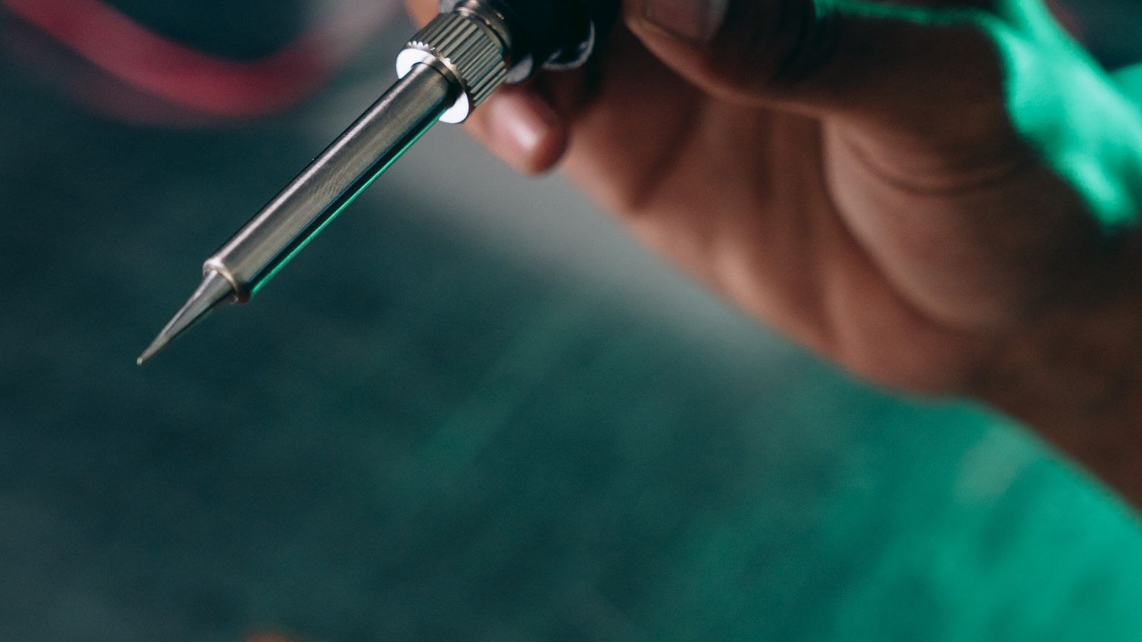
- Temperature-controlled soldering iron with a fine chisel tip, ideally 2mm to 3mm wide. A fixed-wattage pencil iron with no thermostat is the single biggest cause of lifted pads.
- Rosin-core solder, 0.6mm to 0.8mm diameter. Leaded 60/40 flows at a lower temperature and is far more beginner-friendly; lead-free requires more heat and more patience.
- Flux pen or paste to help solder wet the pad quickly.
- 22 to 20 AWG stranded hookup wire for runs under a couple of metres, heavier for longer feeds.
- Wire strippers, flush cutters, and fine tweezers.
- Heat-shrink tubing in a size that slips over the joint, plus a heat gun or lighter used carefully.
- Isopropyl alcohol and a lint-free cloth for cleaning flux residue.
- Multimeter for continuity and polarity checks.
- Kapton tape or a small clamp to hold the strip flat while you work.
Set the Right Iron Temperature
Aim for roughly 315 to 340 degrees Celsius, or about 600 to 650 degrees Fahrenheit, for leaded solder. Lead-free needs closer to 370 Celsius. Running cooler than this feels safer but is actually worse: you end up holding the tip on the pad for six or seven seconds waiting for the solder to flow, and that soak time is exactly what delaminates copper from the backing.
The target is a joint made in two seconds or less. Hot and fast beats cool and slow every single time. Wipe the tip on a damp sponge or brass wool and re-tin it before each joint, because an oxidized tip transfers heat poorly and tempts you to linger.
Step-by-Step: Soldering LED Strip Connectors
- Cut the strip on the marked line. Every strip has printed scissor icons or a dashed cut line running through the middle of the copper pads. Cut exactly there with flush cutters or sharp scissors so you leave half a pad on each side. Cutting anywhere else orphans an LED segment that will never light.
- Expose the pads. On a bare strip the pads are already visible. On a waterproof strip, slit the silicone sleeve with a hobby knife and peel back about 10mm, then scrape any residual silicone or conformal coating off the copper with the knife edge held flat.
- Clean and flux the pads. Wipe with isopropyl alcohol, let it flash off, then apply a small dab of flux to each pad. Flux is what lets solder wet the copper in under two seconds.
- Tin the pads. Touch the iron tip to the pad and feed a small amount of solder immediately. You want a low, shiny dome, not a tall blob. Lift the iron the instant the solder flows. Repeat for the second pad. If a pad refuses to take solder, add more flux rather than more heat.
- Prepare and tin the wires. Strip about 3mm of insulation, twist the strands, then tin them so they turn into a stiff solid pin. Untinned strands fray and bridge across to the neighbouring pad.
- Anchor the strip. Tape the strip down to your bench with Kapton tape so it cannot slide. Trying to hold strip, wire, iron, and solder simultaneously with two hands is how joints get cold.
- Join the wire to the pad. Lay the tinned wire end flat on the tinned pad, press the iron tip down onto both for one to two seconds until the two solder deposits merge, then remove the iron and hold the wire still for three seconds while it solidifies. Do not add fresh solder unless the joint looks starved.
- Inspect the joint. A good joint is shiny, slightly concave, and shows the wire outline through the solder. A dull, grainy, or ball-shaped joint is a cold joint. Reflow it with flux rather than piling on more solder.
- Insulate. Slide heat-shrink tubing over the joint and shrink it, or on a waterproof strip apply a bead of neutral-cure silicone over the exposed copper. Bare pads sitting behind a metal channel are a short circuit waiting to happen.
- Test before mounting. Connect to the driver at low brightness and confirm the whole segment lights evenly. Only then peel the adhesive backing and mount.
Getting Polarity Right
Single-color strips are marked with a plus and minus at each cut point. Red wire goes to plus, black to minus. Get it backwards and nothing lights, though most strips survive the mistake because the LEDs simply block reverse current. Correct the wiring and they wake up.
RGB strips carry four pads, usually labelled 12V or 24V plus, then R, G and B. The supply pad is common and the three color pads switch to ground inside the controller. RGBW adds a fifth pad. The reliable way to keep track across several joints is to keep the strip oriented the same direction on your bench for every connection, so the pad order never mirrors on you. Mark the supply wire with a stripe of tape and follow it down the run.
Addressable Strips Add a Direction Arrow
Addressable strips have a data pad and a printed arrow showing which way the signal travels. Data must flow in the arrow direction, so when you splice two lengths, the arrow on the second length must continue pointing away from the controller. Reversing it produces a strip that lights the first segment and then nothing. Keep the data wire short at the joint and, on long runs, twist it loosely with the ground wire to reduce interference.
Safety Notes Worth Taking Seriously
Always unplug the driver before soldering. Working on a live strip risks shorting the supply across your iron tip. Solder fumes are flux vapour rather than lead vapour, but they are still an airway irritant, so work near an open window or a small fume extractor fan. Wear eye protection, because flux spits when it hits a hot tip. Wash your hands after handling leaded solder and never eat at the bench. Finally, rest the iron in a proper stand every time you put it down, not on the bench edge.
Troubleshooting Common Problems
- Pad lifted off the strip. The backing delaminated from too much heat. Scrape back 5mm of the green or white top layer to expose the copper trace underneath, tin that trace, and solder there. Then support the repair with a blob of hot glue for strain relief.
- Solder will not stick. Almost always oxidation or leftover conformal coating. Add flux, scrape the pad lightly, and re-tin the iron.
- One color channel dead on an RGB run. Check for a cold joint on that specific pad and confirm the wire has not swapped positions at the joint.
- Segment dims toward the far end. Voltage drop, not a soldering fault. Feed power to both ends of the run, or step up to a 24V strip which tolerates longer spans.
- Bridged pads. Two adjacent pads joined by stray solder. Add flux, drag the tip across the bridge toward the edge, or lift the excess with desoldering braid.
- Intermittent flicker. Usually a joint that looks fine but has a hairline crack from flexing. Reflow it and add heat-shrink strain relief.
Mistakes That Ruin Otherwise Good Strips
The most common error is holding the iron on the pad too long, which cooks the adhesive under the copper. The second is stressing the joint by pulling the wire sideways as the strip is mounted, so always leave a small service loop and secure the wire with a clip an inch from the joint. The third is buying cheap strips with paper-thin copper and blaming the technique when the pads lift on the first attempt. Quality matters here: the well-built LED strip lights and dedicated LED tape lights worth soldering use thicker copper that tolerates a second attempt if your first joint goes wrong.
Frequently Asked Questions
Can I solder a 5V addressable strip the same way?
Yes, the technique is identical. The only difference is that 5V strips are more sensitive to voltage drop, so keep wire runs short and inject power every few metres.
What if my strip is already mounted on a wall?
Do not solder in place. Heat radiating off the iron can scorch paint and you cannot support the strip properly. Peel back the section you need, work on a bench, then remount.
Do I need to remove flux residue?
Rosin flux is not corrosive once cooled, but it attracts dust. A quick wipe with isopropyl alcohol keeps things clean.
Is a soldered joint safe inside a ceiling or cove?
It is, provided the joint is fully insulated with heat-shrink and the strip is rated for the location. For permanent installations, hardwired LED strip lights designed to be fed from a junction box are the appropriate choice, and local electrical rules may require an enclosure for the mains-side connection.
Final Thoughts
Soldering LED strips rewards preparation far more than skill. Set the iron hot enough to work fast, flux and tin both surfaces before they ever meet, anchor everything so nothing moves, and treat two seconds as your hard limit on the pad. Insulate every joint, verify polarity and data direction before you power up, and always test the segment on the bench rather than after it is glued inside a channel. Do that and your connections will outlast the adhesive, the controller, and probably the LEDs themselves, which is exactly what you want from a run you never intend to touch again.